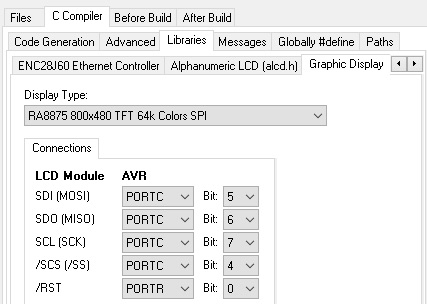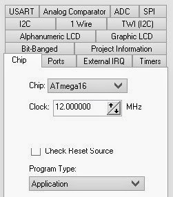


Project Information node and completing the comments in the corresponding The next step, before generating the actual program code, is to specify some comments regarding our The obtained time period between two interrupts will be 0.2 seconds, matching our requirement with a 0% Values for Timer 1 configuration registers:Īs can be seen in the above window, the 16 MHz system clock will be divided by 64 in order to obtain a Timerġ Clock Value of 250 kHz and the OCR1A register will be initialized with the value 0xC34F. Reset to 0 and a Timer 1 compare with OCR1A match interrupt will be generated.īy clicking on the Apply button in the Requirements panel, the CodeWizardAVR will establish the required When this will occur, the TCNT1 register will be automatically In this operating mode the Timer 1 will count pre-scaled system clock pulses until the TCNT1 register will beĮqual with the value of the OCR1A register. Timer1 will be used, so click on the corresponding tab:Īs we need a Timer 1 compare match interrupt after each 200 ms, we must select the operating Mode as:ĬTC top=OCR1A, specify the Period value: 200 ms in the Requirements panel and check the Interrupt on Timers/Counters node of the CodeWizard’s tree.Ī Timers/Counters Settings panel will be displayed: The next step is to configure a Timer/Counter to generate an interrupt after each 200 ms. The next step is to configure the PORTD pins PD0 to PD7 as outputs.Ī new configuration panel for Port Settings will be displayed:Ĭlick on the Port D tab in order to select the PORTD configuration:Īs can be seen, the Port D Data Direction for all I/O pins is set by default as inputs (In).Ĭlick on each Bit 0 to Bit 7 button in order to set the I/O pins as outputs:Īs the LEDs must be OFF after chip reset, the potential of their cathodes must be +5V, so the Output Valuesįor Port D Bit 0 to Bit 7 must be set to 1 by clicking on the corresponding buttons: In the Chip Settings panel, select the Chip type: ATmega328P and Clock frequency: 16 MHz. The CodeWizardAVR will be launched and the following window will be displayed: Select the AT90, ATtiny, ATmega option and click on the OK button. menu command.Ī dialog window will be displayed, allowing selecting the AVR chip family for which the CodeWizardAVR will This willĮxecute the File|New|Project Using the CodeWizardAVR. The programmer’s cable connector with the board’s ICSP header pin 1.Ĭonnect the USB connector of the Arduino board to another USB port of your computer. These outputsĬorrespond to PORTD pins PD0.PD7 of the microcontroller.Ĭonnect each LED’s anode, using a 1k resistor, to the pin marked 5V of the board’s POWERĬonnect the AVRISP MkII programmer to an USB port of your computerĬonnect the AVRISP MkII programmer to the ICSP header. If it is not already installed, solder a 6 pin header to the location marked ICSP on the Arduino UNOĬonnect the cathodes of 8 LEDs to the outputs marked DIGITAL 0.7 on the board. Make the following hardware preparations:
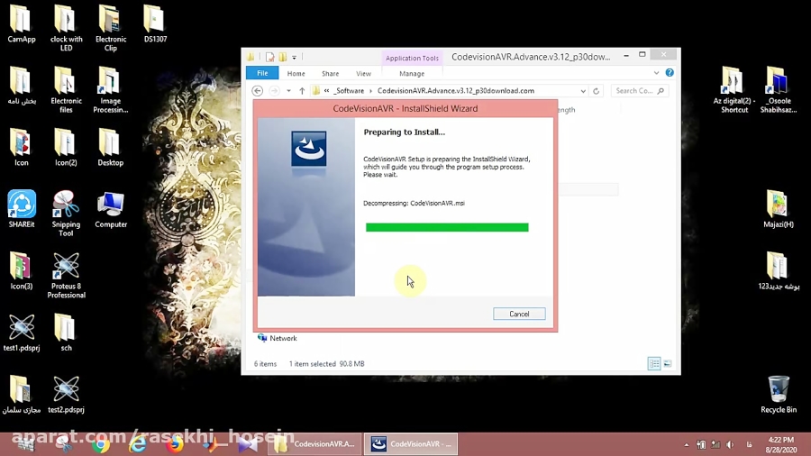
#Codevision avr v3 installer windows
Please note that Administrator privileges are required under Windows for installing and using When prompted, use the default installation directory suggested by the installer.

#Codevision avr v3 installer install
The example is a simple program for the Atmel ATmega328 microcontroller on an Arduino UNO board.ĭownload and install Atmel Studio from Install the CodeVisionAVR C Compiler by executing the CodeVisionAVR.msi installer. The purpose of this document is to guide the user through the preparation, building and debugging of anĮxample C program using the CodeVisionAVR V3.03 or later C compiler extension for Atmel Studio 6.1 or Building the Project and Programming the Chip. No part of this document may be reproduced in any form except by written permission of the author.ġ. Getting Started with the CodeVisionAVR Extension for Atmel Studio 6.1Ĭopyright © 2012-2013 Pavel Haiduc and HP InfoTech S.R.L. Tutorial Penggunaan CodeVision AVR dengan Bahasa C


 0 kommentar(er)
